Overview: The Spatial Power of the Digital Twin
OverviewA LiDAR-based virtual tour is not a simple panoramic photograph; it is a spatially referenced digital twin anchored to real physical dimensions. When you navigate our 360° scans, you are interacting with millions of laser data points captured on-site so that your as-built drawings achieve typical ±1 cm (~0.4 in) accuracy on clearly visible interior walls.
Whether you are verifying ceiling heights for secondary suite clearances, assessing egress corridors under the BC Building Code, or collaborating with structural engineers remotely, the digital twin interface provides an immutable baseline for your project.
Step 1: Navigate 360 Environment via Scan Points
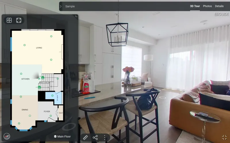
Phase 01To maximize the utility of the digital twin, our interface provides three intuitive movement and inspection controls tailored for design and permit reviews:
- Visual Halos (Floor Rings): Click the circular halos projected onto the floor within the 360° view to 'walk' naturally through the building. This provides immediate spatial context for BC Building Code assessments, such as evaluating egress travel distances, door swing clearances, and ceiling height transitions.
- Green Scan Points (Floor Plan Teleportation): Click any numbered point on the interactive 2D floor plan to jump straight to that room. Each station represents an authentic 360-degree LiDAR capture, ensuring no partition or mechanical closet is overlooked.
- 360° Panoramic Pan & Tilt: Click and drag anywhere in the view to conduct a thorough site audit. Inspect ceiling plenum drops, evaluate existing plumbing stacks, check electrical sub-panels, and inspect beam penetrations without scheduling disruptive return site visits.
Step 2: Extract As-Built Data & Technical Details
Phase 02In the top-right corner of the tour viewer, the technical menu provides direct access to the data layers required for permit drafting and municipal submissions:
- Photos Tab: Displays high-resolution Ricoh THETA Z1 360° & site detail photos documenting critical mechanical connections, service entries, electrical panels, and structural framing conditions that require extra visual clarity.
- Details Tab: The heart of the as-built documentation package. Displays approximate room dimensions and floor areas, ceiling heights, per-floor interior areas, and overall gross floor area calculations—useful for evaluating Floor Area Ratio (FAR) and site coverage alongside a BCLS survey.
- Map Tab: Integrates municipal GIS and geographic parcel orientation to verify property setbacks, lane access, and North arrow alignment against municipal survey data.
Step 3: Download Vector PDF Floor Plans
Phase 03Need printable, dimensioned vector drawings for site walk-throughs, trade bidding, or municipal pre-application meetings? You can download complete floor plans directly from the viewer with just two clicks:
- In the tour viewer top menu (or hamburger menu), click “Details”.
- Right at the top under the Floor Plan header, select “Download PDF Floor Plan” (or Download PDF Tag Data).
- The dimensioned vector floor plan will download immediately for municipal review, trade estimates, or offline markup.
Step 4: Execute LiDAR-Integrated Measurement Modes
Phase 04Our virtual tours allow you to extract real-world dimensions directly from the LiDAR data cloud. The viewer offers three specialized measurement modes tailored to different drafting and verification requirements:
Floor Plan 2D
1. Take Measurements: Right-click and drag on the floor plan to measure any room dimension, hallway, or partition.
2. Pan & Zoom: Left-click and drag to reposition, and use the mouse wheel to zoom into wall thicknesses.
Vertical Wall Plane
1. Define Wall Plane: Right-click and drag on the floor plan along any wall to lock a vertical plane.
2. Measure in Image: Double-click in the 360° image for start and end points (select more points for chained heights).
3D Image Point
1. Set Points: Double-click in the image to set start and end points.
2. Multi-Panorama Triangulation: Switch to a second scan position with visibility of the same points and double-click each in the same order (camera height must be identical).
Step 5: Coordinate Remote Audits with Stakeholders
Phase 05Permit success requires seamless collaboration between designers, structural engineers, trade contractors, and municipal reviewers. The tour interface's built-in Share function eliminates communication breakdowns:
- Direct Angle URL Sharing: Generate a custom link that opens the digital twin at your exact camera coordinates, zoom level, and active measurement markers.
- Structural Coordination: Send specific beam pocket conditions directly to your Structural Engineer (P.Eng.) so they can confirm Schedule B framing requirements without billing for an extra on-site inspection.
- Municipal Plan Examiner Clarifications: When city examiners issue review comments (RFIs) regarding spatial separation, plumbing vents, or firewall continuity, share the digital twin link to provide immediate visual proof.
Get Permit-Ready with LiDAR Accuracy
Permit ReadyStop relying on hand-sketched tape measurements that lead to framing change orders and municipal re-submission delays. Our on-site iGUIDE PLANIX Pro LiDAR scanning delivers spatial baselines with typical ±1 cm (~0.4 in) accuracy on clearly visible interior walls (with exterior dimensions confirmed by hand) needed to clear permit counters across Vancouver, Surrey, Burnaby, Richmond, and Coquitlam.
Direct Project Feasibility: (604) 335-2009 (Mon–Fri 8:30am–5pm)
FAQ: LiDAR Precision vs. the Tape Measure
FAQHow does LiDAR differ from standard 360 photography?
Standard 360 photography is purely optical imagery without depth context. LiDAR (Light Detection and Ranging) utilizes pulsed lasers to measure the time-of-flight distance to solid surfaces, creating a 3D coordinate point cloud. This allows you to extract real-world dimensions and export CAD base plans (DWG/DXF), PDF, ESX, and 3D models with typical ±1 cm (~0.4 in) accuracy on clearly visible interior walls (while hidden cavities/framing, narrow/cluttered or reflective surfaces like glass/mirrors, and exterior dimensions are confirmed manually).
Can these measurements be used for BC Building Code Schedules?
Yes. Our LiDAR-derived dimensional data provides the verified spatial foundation required by building designers and Professional Engineers (P.Eng.) to accurately draft structural layouts, verify fire separations, calculate ceiling volumes, and stamp Letters of Assurance.
Why is LiDAR essential for commercial and residential renovations?
In commercial renovations, accuracy ensures trades build to the exact existing conditions, preventing HVAC ducting clashes, electrical layout re-work, and costly construction delays. For residential projects, LiDAR establishes vertical connectivity across multi-storey framing, verifying floor-to-floor heights, out-of-plumb walls, and structural spans so you can order custom cabinetry, doors, and structural beams with total confidence.
Why is this critical for high-density (SSMUH) multiplex projects?
Under BC Bill 44 Small-Scale Multi-Unit Housing (SSMUH) rules, density calculations leave zero margin for error. Every centimeter of Floor Area Ratio (FAR), lot coverage, and setback distance counts toward maximum allowable unit yields. Capturing the exact existing footprint with LiDAR helps prevent municipal rejection due to manual measurement discrepancies.

Canadian Blueprint Inc.
BC Building Design & Permit Drawings
Published • Updated